GB/T 15704-2025 PDF English
Price & Delivery
US$275.00 · In stock · Download in 9 secondsGB/T 15704-2025: Road vehicles - Light alloy wheels - Impact test method
Delivery: 9 seconds. True-PDF full-copy in English & invoice will be downloaded + auto-delivered via email. See step-by-step procedure
Status: Valid
GB/T 15704: Historical versions
| Standard ID | USD | BUY PDF | Delivery | Standard Title (Description) | Status |
| GB/T 15704-2025 | 275 | Add to Cart | Auto, 9 seconds. | Road vehicles - Light alloy wheels - Impact test method | Valid |
| GB/T 15704-2012 | 70 | Add to Cart | Auto, 9 seconds. | Road vehicles -- Light alloy wheels -- Impact test procedure | Valid |
| GB/T 15704-1995 | 199 | Add to Cart | 2 days | Passenger cars--Wheels--Impact test procedure | Obsolete |
Click to Preview this PDF
Similar standards
GB/T 15704-2025: Road vehicles - Light alloy wheels - Impact test method
---This is an excerpt. Full copy of true-PDF in English version (including equations, symbols, images, flow-chart, tables, and figures etc.), auto-downloaded/delivered in 9 seconds, can be purchased online: https://www.ChineseStandard.net/PDF.aspx/GBT15704-2025GB NATIONAL STANDARD OF THE PEOPLE'S REPUBLIC OF CHINA ICS 43.040.50 CCS T 22 GB/T 15704-2025 / ISO 7141.2022 Replacing GB/T 15704-2012 Road vehicles - Light alloy wheels - Impact test method (ISO 7141.2022, Road vehicles - Light alloy wheels - Lateral impact test, IDT) Issued on: JUNE 30, 2025 Implemented on: JANUARY 1, 2026 Issued by. State Administration for Market Regulation; Standardization Administration of PRC.
Table of Contents
Foreword... 3 1 Scope... 5 2 Normative references... 5 3 Terms and definitions... 5 4 Test equipment... 5 5 Calibration... 6 6 Test procedures... 6 7 Failure criteria... 7 Appendix A (Informative) Supplementary instructions for impact testing machine calibration... 11 Road vehicles - Light alloy wheels - Impact test method1 Scope
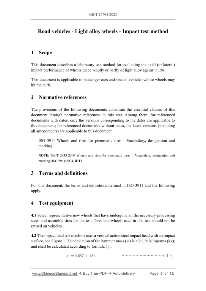
This document describes a laboratory test method for evaluating the axial (or lateral) impact performance of wheels made wholly or partly of light alloy against curbs. This document is applicable to passenger cars and special vehicles whose wheels may hit the curb.2 Normative references
The provisions of the following documents constitute the essential clauses of this document through normative references in this text. Among them, for referenced documents with dates, only the versions corresponding to the dates are applicable to this document; for referenced documents without dates, the latest versions (including all amendments) are applicable to this document. ISO 3911 Wheels and rims for pneumatic tires - Vocabulary, designation and marking NOTE. GB/T 2933-2009 Wheels and rims for pneumatic tyres – Vocabulary, designation and marking (ISO 3911.2004, IDT)3 Terms and definitions
For this document, the terms and definitions defined in ISO 3911 and the following apply.4 Test equipment
4.1 Select representative new wheels that have undergone all the necessary processing steps and assemble tires for the test. Tires and wheels used in this test should not be reused on vehicles. 4.2 The impact load test machine uses a vertical action steel impact head with an impact surface, see Figure 1.The deviation of the hammer mass (m) is ±2%, in kilograms (kg), and shall be calculated according to formula (1). Where m -- the mass of the hammer, in kilograms (kg); W -- the maximum vertical static load of the wheel specified by the wheel or vehicle manufacturer, in kilograms (kg). If not specified, the maximum value of the rated load of the wheel and tire shall be taken. 4.3 The calibration mass is 1000 kg.5 Calibration
A calibration mass of 1000 kg is applied vertically to the mounting center of the wheel through the calibration connector, as shown in Figure 2.When measured at the center of the steel beam, the vertical deformation is within the range of 7.5 mm±0.75 mm. The drop height of the hammer should be 230 mm±2 mm. This height shall be sufficient to allow the hammer to travel a distance of 25.4 mm before contacting the tire, taking 12.31+0.3 0 ms. The loss of hammer velocity due to friction in the test equipment is compensated by the adjusted drop height (ADH) to achieve a measured velocity equivalent to that of a 230 mm free fall. Prior to impacting the tire, a velocimeter is used in conjunction with a gate grating to measure the hammer velocity. Starting at a calibrated height of 230 mm, the height is increased in 2 mm increments until the hammer passes the gate grating, taking 12.31+0.3 0 ms. If the drop height increment exceeds 10 mm during calibration, the tester should be removed from service, and maintenance shall be performed to reduce friction in the system. For equipment that passes calibration, all tests shall be conducted at the adjusted drop height until the next calibration. Appendix A gives guidance and examples for measuring the time required to cover a distance.6 Test procedures
6.1 Install the test wheel and tire assembly on the testing machine so that the impact load is applied to the wheel flange. The wheel axis shall be at an angle of 13°±1° to the vertical, with the highest point of the wheel flange facing the impact hammer. The tires used for the test shall be those specified by the vehicle manufacturer. If no tire is specified, a tubeless radial tire with the minimum nominal section width applicable to the wheel shall be used. The inflation pressure shall be the value specified by the vehicle manufacturer. If no such value is specified, the inflation pressure shall be 200 kPa. During the entire test process, the ambient temperature shall be maintained at 10 ℃~30 ℃. 6.2 Ensure that the wheel is assembled to the hub fixture using fasteners that are consistent with the actual installation on the vehicle and have representative dimensions. Tighten the nuts or bolts by hand to the specified torque value, or tighten them using the method recommended by the vehicle or wheel manufacturer. Due to the diversity of wheel center section designs, sufficient locations on the circumference of the wheel flange are selected for impact testing to ensure the completeness of the center section evaluation. A new wheel is used for each test.7 Failure criteria
If any of the following conditions occur, the test wheel is considered to have failed. a) It can be seen that the crack penetrates the cross-section of the center part of the wheel, see Figure 3; b) The center part of the wheel is separated from the rim; c) Within 1 minute, all tire pressure leaks out. If only the wheel is deformed or the section of the rim directly impacted by the hammer is broken, the test wheel is not considered to have failed. NOTE 1.A fracture or separation of the outer flange below the hammer, as shown in Figure 3 (at the outer flange), does not constitute a failure to meet the acceptance criteria. NOTE 2.Any changes to components other than the wheel body (such as pneumatic parts) shall not be used as a basis for judging the test results. ......Source: Above contents are excerpted from the full-copy PDF -- translated/reviewed by: www.ChineseStandard.net / Wayne Zheng et al.