GB/T 18430.1-2024 PDF EnglishUS$1070.00 · In stock · Download in 9 seconds
GB/T 18430.1-2024: Water chilling(heat pump) packages using the vapor compression cycle - Part 1: Water chilling(heat pump) packages for industrial & commercial and similar applications Delivery: 9 seconds. True-PDF full-copy in English & invoice will be downloaded + auto-delivered via email. See step-by-step procedure Status: Valid GB/T 18430.1: Historical versions
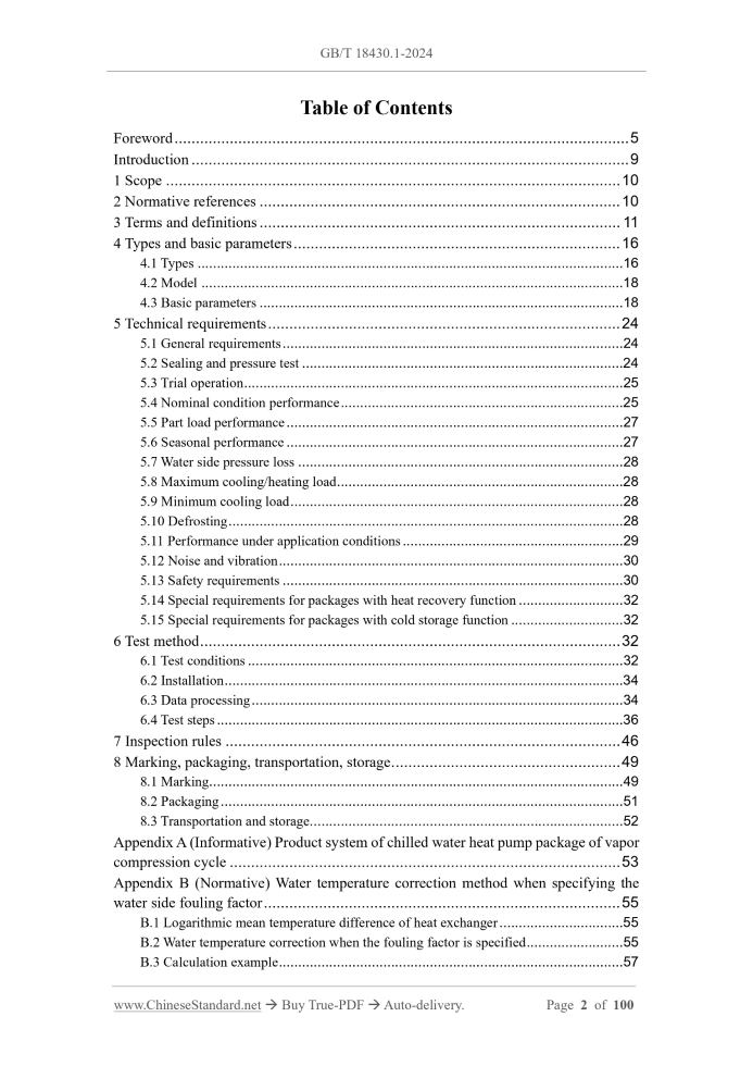
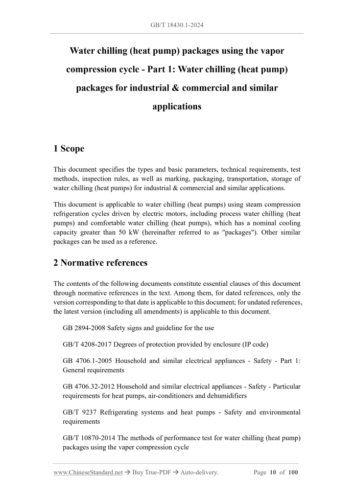
Similar standardsGB/T 18430.1-2024: Water chilling(heat pump) packages using the vapor compression cycle - Part 1: Water chilling(heat pump) packages for industrial & commercial and similar applications---This is an excerpt. Full copy of true-PDF in English version (including equations, symbols, images, flow-chart, tables, and figures etc.), auto-downloaded/delivered in 9 seconds, can be purchased online: https://www.ChineseStandard.net/PDF.aspx/GBT18430.1-2024 GB NATIONAL STANDARD OF THE PEOPLE’S REPUBLIC OF CHINA ICS 27.200 CCS J 73 Replacing GB/T 18430.1-2007 Water chilling (heat pump) packages using the vapor compression cycle - Part 1.Water chilling (heat pump) packages for industrial & commercial and similar applications Issued on: SEPTEMBER 29, 2024 Implemented on: APRIL 01, 2025 Issued by. Status Administration for Market Regulation; National Standardization Administration. Table of ContentsForeword... 5 Introduction... 9 1 Scope... 10 2 Normative references... 10 3 Terms and definitions... 11 4 Types and basic parameters... 16 4.1 Types... 16 4.2 Model... 18 4.3 Basic parameters... 18 5 Technical requirements... 24 5.1 General requirements... 24 5.2 Sealing and pressure test... 24 5.3 Trial operation... 25 5.4 Nominal condition performance... 25 5.5 Part load performance... 27 5.6 Seasonal performance... 27 5.7 Water side pressure loss... 28 5.8 Maximum cooling/heating load... 28 5.9 Minimum cooling load... 28 5.10 Defrosting... 28 5.11 Performance under application conditions... 29 5.12 Noise and vibration... 30 5.13 Safety requirements... 30 5.14 Special requirements for packages with heat recovery function... 32 5.15 Special requirements for packages with cold storage function... 32 6 Test method... 32 6.1 Test conditions... 32 6.2 Installation... 34 6.3 Data processing... 34 6.4 Test steps... 36 7 Inspection rules... 46 8 Marking, packaging, transportation, storage... 49 8.1 Marking... 49 8.2 Packaging... 51 8.3 Transportation and storage... 52 Appendix A (Informative) Product system of chilled water heat pump package of vapor compression cycle... 53 Appendix B (Normative) Water temperature correction method when specifying the water side fouling factor... 55 B.1 Logarithmic mean temperature difference of heat exchanger... 55 B.2 Water temperature correction when the fouling factor is specified... 55 B.3 Calculation example... 57 Water chilling (heat pump) packages using the vapor compression cycle - Part 1.Water chilling (heat pump) packages for industrial & commercial and similar applications1 ScopeThis document specifies the types and basic parameters, technical requirements, test methods, inspection rules, as well as marking, packaging, transportation, storage of water chilling (heat pumps) for industrial & commercial and similar applications. This document is applicable to water chilling (heat pumps) using steam compression refrigeration cycles driven by electric motors, including process water chilling (heat pumps) and comfortable water chilling (heat pumps), which has a nominal cooling capacity greater than 50 kW (hereinafter referred to as "packages"). Other similar packages can be used as a reference.2 Normative referencesThe contents of the following documents constitute essential clauses of this document through normative references in the text. Among them, for dated references, only the version corresponding to that date is applicable to this document; for undated references, the latest version (including all amendments) is applicable to this document. GB 2894-2008 Safety signs and guideline for the use GB/T 4208-2017 Degrees of protection provided by enclosure (IP code) GB 4706.1-2005 Household and similar electrical appliances - Safety - Part 1. General requirements GB 4706.32-2012 Household and similar electrical appliances - Safety - Particular requirements for heat pumps, air-conditioners and dehumidifiers GB/T 9237 Refrigerating systems and heat pumps - Safety and environmental requirements GB/T 10870-2014 The methods of performance test for water chilling (heat pump) packages using the vaper compression cycle5 Technical requirements5.1 General requirements 5.1.1 The package shall be manufactured according to the drawings and technical documents approved by the prescribed procedures. 5.1.2 The installation of each component of the package shall be firm and reliable; the installation of pipeline accessories shall be horizontal and vertical; the arrangement shall be neat; the compressor shall have anti-vibration measures. 5.1.3 The package shall use non-toxic, odorless and flame-retardant thermal insulation materials; no condensation shall be generated on the insulation layer during normal operation of the package. 5.1.4 The package can be equipped with a cold (hot) water circulation pump according to user requirements or actual use; its flow rate and head shall be able to ensure the normal operation of the package. 5.1.5 The package shall have functions such as motor overload protection, phase sequence protection (three-phase motor package), water system flow interruption protection, antifreeze protection, system high and low pressure protection, etc. 5.1.6 The appearance of the package shall comply with the following requirements. a) Ferrous metal parts shall be treated with anti-corrosion; b) The surface of electroplated parts shall be smooth and uniform in color; there shall be no defects such as peeling, bottom exposure, pinholes, obvious spots, scratches; c) The surface of painted parts shall be flat, with uniform coating and color; there shall be no obvious defects or damage such as bubbles, flow marks, wrinkles; there shall be no holiday or primer exposure; d) The surface of decorative plastic parts shall be flat and smooth, with uniform color; there shall be no cracks, bubbles, obvious shrinkage defects. 5.2 Sealing and pressure test 5.2.1 Sealing 5.2.1.1 Airtightness The refrigeration system of the package shall have good sealing performance. When the airtightness test is carried out according to 6.4.1.1.1, there shall be no leakage in any part of the refrigeration system of the package. 5.2.1.2 Vacuum test When the vacuum test is carried out according to 6.4.1.1.2, there shall be no leakage in the refrigeration system of the package; the pressure rise shall meet the following requirements. a) For packages with a single system cooling capacity of no more than 300 kW, the pressure rise of each system shall not be greater than 100 Pa; b) For packages with a single system cooling capacity of more than 300 kW, the pressure rise of each system shall not be greater than 150 Pa. 5.2.2 Pressure test When the package is pressure tested according to 6.4.1.2, there shall be no abnormal deformation and leakage in each pipeline component and connection. 5.3 Trial operation The package shall be able to start normally during the trial operation test; there shall be no abnormality during operation. For large packages that need to be assembled on site or other packages that do not meet the conditions for exit-factory trial operation, only the compressor head operation test and the electronic control system simulation test can be carried out before leaving the factory, or the trial operation test can be carried out on site in agreement with the user. 5.4 Nominal condition performance 5.4.1 Nominal refrigeration 5.4.1.1 The measured nominal cooling capacity of the package shall not be less than 95% of the stated value. 5.4.1.2 The measured nominal cooling power consumption of the package shall not be greater than 110% of the stated value. 5.4.1.3 The measured nominal cooling performance coefficient of the package shall meet the following requirements. a) Comfortable package. It shall not be lower than the limit value specified in Table 9, Table 10 or Table 11; it shall not be lower than 95% of the stated value; b) Process package. It shall not be lower than 95% of the stated value; 6.1.1.1 The atmospheric pressure of the test site shall be within the range of (101 ± 10) kPa. If it exceeds the range, it shall be corrected or negotiated according to relevant standards. 6.1.1.2 The test environment room of air-cooling and evaporative cooling packages shall be able to ensure that the distance between the air exhaust side of the package is not less than 1.8 m; the distance between the other surfaces of the package and the room is not less than 0.9 m. After the package is installed in place before the test (not turned on), the air speed at any point 0.5 m away from the package shall not be greater than 2 m/s. 6.1.2 Test resources 6.1.2.1 It should use a power supply with voltage stabilization function. Except for the moment when the package is started or stopped, the power supply shall meet the following requirements. a) The frequency deviation does not exceed the range of ±0.5 Hz; b) The voltage deviation does not exceed the range of ±5% of the rated voltage. 6.1.2.2 The water quality provided to the package's circulating cooling water system and circulating chilled water system shall comply with the relevant provisions of GB/T 29044. 6.1.3 Instruments 6.1.3.1 The type and accuracy of the test instruments shall comply with the provisions of GB/T 10870-2014; it shall be verified or calibrated by the metrology inspection department and within the applicable validity period. 6.1.3.2 The installation of the test flow meter shall comply with the provisions of F.4 in Appendix F. 6.1.3.3 The frequency range of the vibration measuring instrument shall include 10 Hz ~ 1000 Hz. The relative sensitivity within this frequency range shall be based on the relative sensitivity of 160 Hz; the relative sensitivity of other frequencies shall be within the range of 90% ~ 105% of the reference sensitivity. 6.1.4 Tooling and equipment 6.1.4.1 The dry and wet bulb temperatures on the air side of the package shall be measured, using a measuring device that meets the requirements of Appendix B of GB/T 10870-2014. 6.1.4.2 The pressure loss and temperature on the water side of the package shall be measured, using the water side pressure loss and temperature measuring device specified in Appendix F. 6.2 Installation 6.2.1 The package under test shall be installed firmly, meet the requirements of the product manual or comply with the relevant regulations of the manufacturer. 6.2.2 The installation platform or foundation of the package under test shall not generate additional vibration or resonate with the package. The vibration value of the installation platform or foundation during the operation of the package shall be less than 10% of the maximum vibration value of the package under test. 6.2.3 If necessary, fill the appropriate amount of refrigerant according to the nameplate specifications. The amount of refrigerant shall not be adjusted during the test. 6.2.4 First complete the connection between the package and the water system of the test device; ensure that the opening and closing states of the valves of the test device are correct; then arrange the measurement sensors required for the test; finally connect the power supply of the package. 6.3 Data processing 6.3.1 During the test, the tolerances of the parameters of each application condition shall comply with the provisions of Table 16 and Table 17.When non-steady state occurs in the heating test, the tolerances of the operating parameters shall comply with the provisions of Table G.1 in Appendix G. Note 1.Average variation range - The deviation between the measured average value and the specified value of each test condition. Note 2.Maximum variation range - The deviation between the maximum and minimum values measured during the test and the specified value of each test condition. Note 3.When the package operates smoothly under various conditions and the tolerances of the relevant readings comply with the provisions of Table 16 and Table 17, the package is considered to have reached a stable operating state. 6.3.2 Data collection and processing shall comply with the provisions of GB/T 10870. 6.4.1.1 Sealing test 6.4.1.1.1 Airtightness test The airtightness test shall be carried out according to the test method specified in 7.8.2.1 or 7.8.2.2 of NB/T 47012-2020. 6.4.1.1.2 Vacuum test The vacuum test shall be carried out in accordance with the following provisions. a) For packages with a single system cooling capacity of ≤ 300 kW, vacuum is pumped to below 266 Pa, the pressure is maintained for more than 10 minutes, the package leakage and pressure rise are checked; b) For packages with a single system cooling capacity of > 300 kW, vacuum is pumped to below 300 Pa, the pressure is maintained for more than 30 minutes, the package leakage and pressure rise are checked. 6.4.1.2 Pressure test The package water system is subjected to a hydraulic pressure test of 1.25 times the design pressure or a gas pressure test of 1.10 times the design pressure; the pressure is maintained for more than 10 minutes; the deformation, leakage and other abnormal conditions of the package water system are checked. 6.4.2 Trial operation test The package is tested for startup and trial operation at rated voltage and rated frequency. The single cooling package is trial tested in the cooling mode; the heat pump package is trial tested in the cooling and heating modes respectively. 6.4.3 Nominal condition performance test 6.4.3.1 Nominal cooling test Adjust the package energy adjustment device to an appropriate position and conduct the test under the specified cooling conditions. The package's actual cooling capacity and cooling power consumption shall be tested in accordance with the following provisions. a) Water-cooling package. Measure the inlet and outlet water temperature and water flow rate on the user side and the heat source side, in accordance with the provisions of Appendix F. The package's cooling capacity is calculated according to formula (4); the heat exchange capacity on the heat source side is calculated according to formula (6); to ensure the effectiveness of the test, the main and auxiliary deviations are calculated by formula (8), which shall not be greater than the allowable deviation specified in 4.2.2 of GB/T 10870-2014. The cooling power consumption shall include the input power of the compressor motor, oil pump motor, operating control circuit (the package with its own water pump shall not include the power of the water pump). b) Air-cooling packages. The inlet and outlet water temperatures and water flow rates are measured on the user side, in accordance with the provisions of Appendix F. The inlet air dry-bulb and wet-bulb temperatures on the heat source side are measured, by arranging an air sampling device in accordance with the provisions of Appendix B of GB/T 10870-2014.The package cooling capacity is calculated according to formula (4). The refrigeration power consumption shall include the input power of the compressor motor, oil pump motor, operation control circuit; it shall also include the input power of the cooling fan on the heat source side (the package with a water pump on the user side water system shall not include the power of the water pump). c) Evaporative cooling packages. The inlet and outlet water temperatures and water flow rates are measured on the user side, in accordance with the provisions of Appendix F. The inlet air dry-bulb and wet-bulb temperatures on the heat source side are measured, by arranging an air sampling device in accordance with the provisions of Appendix B of GB/T 10870-2014.During the measurement period, the package's water replenishment system shall operate automatically. The package cooling capacity is calculated according to formula (4). The refrigeration power consumption shall include the input power of the compressor motor, oil pump motor, operation control circuit, etc.; it shall also include the input power of the water pump and cooling fan of the water sprinkling device on the heat source side (the package with a water pump in the user side water system shall not include the power of the water pump). 6.4.3.2 Nominal heating test The package energy adjustment device is adjusted to an appropriate position; the test is carried out under the specified heating conditions. The package's actual heating capacity and heating power consumption shall be tested in accordance with the following provisions. a) Water-cooling package. The inlet and outlet water temperatures and water flow rates shall be measured on the user side and the heat source side, in accordance with the provisions of Appendix F. The package's heating capacity shall be calculated according to formula (6); the heat exchange capacity on the heat source side shall be calculated according to formula (4); to ensure the effectiveness of the test, the main and auxiliary deviations shall be calculated by formula (8), which shall not be greater than the allowable deviation specified in 4.2.2 of GB/T 10870-2014. The power consumption for heating shall include the input power of the compressor motor, oil pump motor, operation control circuit (the power of the water pump shall not be included in the package with its own water pump in the water system). b) Air-cooling package. The inlet and outlet water temperatures and water flow rate shall be measured on the user side, in accordance with the provisions of Appendix F. The inlet air dry- bulb and wet-bulb temperatures on the heat source side shall be measured, by arranging an air sampling device in accordance with the provisions of Appendix B of GB/T 10870-2014.When defrosting is involved, data collection and calculation shall be carried out in accordance with the provisions of Appendix G. The heating capacity of the package shall be calculated according to formula (6). The power consumption for heating shall include the input power of the compressor motor, oil pump motor, operation control circuit; it shall also include the input power of the fan on the heat source side (the power of the water pump shall not be included in the package with its own water pump in the water system). c) Evaporative cooling packages. The inlet and outlet water temperatures and water flow rates are measured on the user side, in accordance with the provisions of Appendix F. The inlet air dry-bulb and wet-bulb temperatures on the heat source side are measured, by arranging an air sampling device in accordance with the provisions of Appendix B of GB/T 10870-2014.When defrosting is involved, data collection and calculation are carried out in accordance with the provisions of Appendix G. The heating capacity of the package is calculated according to formula (6). The calculation of heating power consumption is the same as that of air-cooling packages, but for packages where the water spraying device still needs to be operated, the input power of the water pump of the water spraying device shall also be included. 6.4.3.3 Calculation of performance parameters 6.4.3.3.1 Refrigerant-water heat exchanger (evaporator) The test method for the heat exchange capacity of the package evaporator adopts the b) Test according to the methods given in 6.4.3, 6.4.4, 6.4.5, Appendix C, Appendix H or Appendix I; c) Verify the output results of the package performance database according to the provisions of 5.11.2 and 5.11.3. 6.4.11 Noise and vibration test 6.4.11.1 Noise test During the performance test under each nominal condition (including nominal cooling, nominal heating, possible nominal heat recovery, nominal cold storage cooling), the noise of the package is measured at the same time; the maximum value measured prevails. The noise measurement points are arranged on the rectangular hexahedron measurement surface specified in JB/T 4330; the average sound pressure level is calculated according to the calculation method specified in JB/T 4330. 6.4.11.2 Vibration test The package shall measure the vibration under the working conditions of the noise test; the maximum value measured under each working condition shall prevail. The measurement shall comply with the following provisions; a) Measurement point location. At 4 different positions on the compressor frame or the 4 bottom corners on the outermost side of the package base, select a position with the maximum relative vibration through investigation and testing, ensure that there is no superposition of external vibration sources; b) Measurement requirements. Reliable and good contact shall be ensured between the sensor and the measurement point; each position shall be measured in the three mutually perpendicular directions of X, Y, Z; c) Measurement results. The maximum value of the measured displacement root mean square value in the three directions is taken as the measured vibration value of the point. The package's operating mode, test conditions, measurement point location shall be recorded during the measurement process. 6.4.12 Electrical safety test 6.4.12.1 Insulation resistance test When the package is confirmed to be de-energized (the package that has just been shut down shall be fully discharged to the ground short circuit), select a suitable insulation resistance meter according to Table 20, to measure the insulation resistance between the package's live parts and easily accessible metal parts. deviations are calculated by formula (D.6), which shall comply with the provisions of 4.2.2 of GB/T 10870-2014. The power consumption of heat recovery shall include the input power of the compressor motor, oil pump motor, operation control circuit (the package with its own water pump in the water system shall not include the power of the water pump). The integrated energy utilization rate of full heat recovery shall be calculated by the test results of the above case I and by formula (D.4). 2) The heat exchanger of the case II package includes three refrigerant-water heat exchangers (if the condenser of the package is not running in the cooling mode, the test method of its heat recovery mode shall refer to the case I of the water- cooling package). The heat recovery amount of the heat recovery heat exchanger of the computer package shall be calculated according to the method and formula (D.1) specified in 6.4.3.2; the heat exchange amount of the condenser of the computer package shall be calculated according to the method and formula (6) specified in 6.4.3.2; the cooling capacity of the computer package shall be calculated according to the method and formula (4) specified in 6.4.3.1.To ensure the validity of the test, the main and auxiliary deviations shall be calculated by formula (D.5), which shall comply with the provisions of 4.2.2 of GB/T 10870-2014. The power consumption of heat recovery shall include the input power of the compressor motor, oil pump motor, operation control circuit, etc. (the power of the water pump shall not be included in the package with its own water pump in the water system). The integrated energy utilization rate of partial heat recovery shall be calculated by the test results of Case II and formula (D.3). b) Air-cooling package 1) Case I. The package heat exchanger includes three heat exchangers. Air- refrigerant heat exchanger, refrigerant-water heat exchanger, refrigerant-water heat recovery heat exchanger. In the heat recovery mode, part of the condensation heat of the refrigerant circulation system is used as the heat recovery amount through the heat recovery heat exchanger. The heat recovery amount of the computer package is calculated according to the method and formula (D.1) specified in 6.4.3.2; the remaining condensation heat is discharged to the air through the air-refrigerant heat exchanger; the cooling capacity of the computer package is calculated according to the method and formula (4) specified in 6.4.3.1. The power consumption of heat recovery shall include the input power of the ......Source: Above contents are excerpted from the full-copy PDF -- translated/reviewed by: www.ChineseStandard.net / Wayne Zheng et al. Tips & Frequently Asked Questions:Question 1: How long will the true-PDF of English version of GB/T 18430.1-2024 be delivered?Answer: The full copy PDF of English version of GB/T 18430.1-2024 can be downloaded in 9 seconds, and it will also be emailed to you in 9 seconds (double mechanisms to ensure the delivery reliably), with PDF-invoice.Question 2: Can I share the purchased PDF of GB/T 18430.1-2024_English with my colleagues?Answer: Yes. The purchased PDF of GB/T 18430.1-2024_English will be deemed to be sold to your employer/organization who actually paid for it, including your colleagues and your employer's intranet.Question 3: Does the price include tax/VAT?Answer: Yes. Our tax invoice, downloaded/delivered in 9 seconds, includes all tax/VAT and complies with 100+ countries' tax regulations (tax exempted in 100+ countries) -- See Avoidance of Double Taxation Agreements (DTAs): List of DTAs signed between Singapore and 100+ countriesQuestion 4: Do you accept my currency other than USD?Answer: Yes. www.ChineseStandard.us -- GB/T 18430.1-2024 -- Click this link and select your country/currency to pay, the exact amount in your currency will be printed on the invoice. Full PDF will also be downloaded/emailed in 9 seconds.Question 5: Should I purchase the latest version GB/T 18430.1-2024?Answer: Yes. Unless special scenarios such as technical constraints or academic study, you should always prioritize to purchase the latest version GB/T 18430.1-2024 even if the enforcement date is in future. Complying with the latest version means that, by default, it also complies with all the earlier versions, technically.How to buy and download a true PDF of English version of GB/T 18430.1-2024?A step-by-step guide to download PDF of GB/T 18430.1-2024_EnglishStep 1: Visit website https://www.ChineseStandard.net (Pay in USD), or https://www.ChineseStandard.us (Pay in any currencies such as Euro, KRW, JPY, AUD).Step 2: Search keyword "GB/T 18430.1-2024". Step 3: Click "Add to Cart". If multiple PDFs are required, repeat steps 2 and 3 to add up to 12 PDFs to cart. Step 4: Select payment option (Via payment agents Stripe or PayPal). Step 5: Customize Tax Invoice -- Fill up your email etc. Step 6: Click "Checkout". Step 7: Make payment by credit card, PayPal, Google Pay etc. After the payment is completed and in 9 seconds, you will receive 2 emails attached with the purchased PDFs and PDF-invoice, respectively. Step 8: Optional -- Go to download PDF. Step 9: Optional -- Click Open/Download PDF to download PDFs and invoice. See screenshots for above steps: Steps 1~3 Steps 4~6 Step 7 Step 8 Step 9 |