TB/T 449-2016 PDF EnglishUS$330.00 · In stock · Download in 9 seconds
TB/T 449-2016: Wheel profile for locomotive and car Delivery: 9 seconds. True-PDF full-copy in English & invoice will be downloaded + auto-delivered via email. See step-by-step procedure Status: Valid TB/T 449: Historical versions
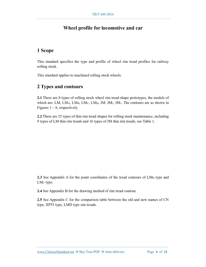
TB/T 449-2016: Wheel profile for locomotive and car---This is an excerpt. Full copy of true-PDF in English version (including equations, symbols, images, flow-chart, tables, and figures etc.), auto-downloaded/delivered in 9 seconds, can be purchased online: https://www.ChineseStandard.net/PDF.aspx/TBT449-2016TB RAILWAY INDUSTRY STANDARD OF THE PEOPLE’S REPUBLIC OF CHINA ICS 45.060.20 S 33 Replacing TB/T 449-2003 Wheel profile for locomotive and car ISSUED ON: MAY 26, 2016 IMPLEMENTED ON: DECEMBER 01, 2016 Issued by: National Railway Administration. Table of ContentsForeword ... 3 1 Scope ... 4 2 Types and contours ... 4 Appendix A (Normative) Point coordinates of tread contour parts ... 12 Appendix B (Informative) Drawing method of rim tread contour ... 14 Appendix C (Informative) Comparison table of old and new names of CN type, XP55 type, LMD type rim treads ... 21 Wheel profile for locomotive and car1 ScopeThis standard specifies the type and profile of wheel rim tread profiles for railway rolling stock. This standard applies to machined rolling stock wheels.2 Types and contours2.1 There are 8 types of rolling stock wheel rim tread shape prototypes, the models of which are: LM, LMA, LMB, LMC, LMD, JM, JM2, JM3. The contours are as shown in Figures 1 ~ 8, respectively. 2.2 There are 25 types of thin rim tread shapes for rolling stock maintenance, including 9 types of LM thin rim treads and 16 types of JM thin rim treads, see Table 1. 2.3 See Appendix A for the point coordinates of the tread contours of LMB type and LMC type. 2.4 See Appendix B for the drawing method of rim tread contour. 2.5 See Appendix C for the comparison table between the old and new names of CN type, XP55 type, LMD type rim treads.Appendix B(Informative) Drawing method of rim tread contour B.1 General The drawing method of rim tread contour is divided into the tread contour drawing method and the rim contour drawing method. See Figure B.1, for the schematic outline of the LMA type rim tread. See Figure B.2, for a schematic outline of the LMB type rim tread. See Figure B.3, for a schematic outline of the LMC type rim tread. See Figure B.4, for a schematic outline of the LMD type rim tread. See Figure B.5, for a schematic outline of the rim tread of LM-28 type, LM-27.5 type, LM-27 type, LM-26 type. See Figure B.6, for a schematic outline of LM-31.5 type, LM-31 type, LM-30 type, LM-29.5 type, LM-29 type, LM type, JM type, JM2 type, JM2 thin rim, JM3 type, JM3 thin rim tread. B.2 Drawing benchmark Take OX, OY as the coordinate axis, axis X as the tread baseline. The symbol markings are as shown in Figure B.1 ~ Figure B.6, respectively, according to different rim tread models. B.3 Method for drawing tread contour curve B.3.1 The specific drawing method of LMA type tread curve is as follows: a) Taking point O as the center and R7 as the radius, draw an arc aa', which intersects the straight line x = L3 on the right side of the Y axis, at point O7; b) Taking point O7 as the center and R7 - R6 as the radius, draw an arc bb', which intersects the straight line x = L2 on the left side of the Y axis, at point O6; c) Taking point O6 as the center and R6 - R5 as the radius, draw an arc cc’; d) Taking point F (-70 + B1, H1) as the center of the circle and R5 as the radius, draw arc dd’. dd’ and cc’ intersect at point O5; e) Taking point O5 as the center and R5 as the radius, draw a straight line gg', that forms an angle of -70° with the X-axis and is tangent to the circle; f) Taking point O6 as the center and R6 as the radius, draw a circle; g) Taking point O7 as the center and R7 as the radius, draw a straight line segment I’I, which has a slope of -1:40 and is tangent to the circle. The tangent point is I’; the abscissa of point I is x = L4; h) Draw a straight line segment IM, which has a slope of -1:15 through point I (the length of IM is determined by the rim width); i) Make MN straight segment, where MN is a 5×5 chamfer. B.3.2 The specific drawing method of LMB type tread curve is as follows: a) Make a curve segment G-H-I, from the point coordinates of the tread contour; b) Using point F (-70 + B1, H1) as the center and R5 as the radius, draw arc dd’. Using point G as the center and R5 as radius, draw arc ee’. dd’ and ee’ intersect at point O5; c) Taking point O5 as the center and R5 as the radius, draw a circle. Draw a straight line gg', that forms an angle of -70° with the X-axis and is tangent to the circle; d) Draw a straight line segment IM, which has a slope of -1:15, through point I (the length of IM is determined by the rim width); e) Make MN straight segment, where MN is a 5×5 chamfer. B.3.3 The specific drawing method of LMC type tread curve is as follows: a) Create a curve segment G-O, from the point coordinates of the tread contour; b) Taking point F (-70 + B1, H1) as the center and R5 as the radius, draw arc dd'. Using point G as the center and R5 as radius, draw arc ee'. dd' and ee' intersect at point O5; c) Taking point O5 as the center and R5 as the radius, draw a circle. Meanwhile, make a straight line gg', that forms an angle of -68°40' with the X-axis and is tangent to the circle; d) Draw a straight line segment OI, which has a slope of -5.5:100 through point O; the abscissa of point I is x = L4; e) Draw a straight line segment IM, which has a slope of -15:100 through point I (the length of IM is determined by the rim width); g) Taking point O7 as the center and R7 + R8 as the radius, draw an arc ff’, that intersects the straight line x = L4 on the right side of the Y-axis, at point O8; h) Taking point O8 as the center and R8 as the radius, draw a circle. Make a straight line segment IM, which has a slope of -1:P (the length of IM is determined by the rim width), and is tangent to the circle; i) Make MN straight segment, where MN is a 5×5 chamfer. B.4 Drawing method of rim profile curve B.4.1 For the LMA type, LMB type, LMC type, LMD type, LM type, LM-31.5 type, LM- 31 type, LM-30 type, LM-29.5 type, LM-29 type, JM type, JM2 type, JM2 thin rim, JM3 type, JM3 thin rim, the specific drawing method of rim contour is as follows: a) Taking point O2 (-70 + L1, H - R2) as the center and R2 as the radius, draw a circle; b) Draw a straight line at x = -70. Taking R1 as the radius, draw a circle, which is tangent to the straight line at x = -70 and circle O2; c) Taking R4 as the radius, draw a circle, which is tangent to the circle O2 and the straight line gg'. B.4.2 The specific drawing methods of rim shapes of LM-28 type, LM-27.5 type, LM- 27 type, LM-26 type are as follows: a) Taking point O2 (-70 + L1, H - R2) as the center and R2 as the radius, draw a circle; b) Draw a straight line of x = -70. Taking R1 as the radius, draw a circle, which is tangent to the straight line of x = -70 and the circle O2; c) Taking point O3 (-70 + L1, H - R3) as the center and R3 as the radius, draw a circle; d) Taking point R4 as the radius, draw a circle, which is tangent to the circle O3 and the straight line gg'. B.5 Trimming of rim tread curve Cut each circle and straight line, to obtain the contour of the corresponding rim tread shape. The tangent (intersection) points are A, B, C, (C'), D, E, G, (H), O, (I'), I, M, N, (P). ......Source: Above contents are excerpted from the full-copy PDF -- translated/reviewed by: www.ChineseStandard.net / Wayne Zheng et al. |